I have been using an NVIS antenna over the winter with good results. I have been able to make contacts with another station when other types of propagation would not work.
Several articles have been written on the several styles of antenna that may be used for NVIS and the operating style that must be used for NVIS operation. NVIS is not for DX’ing it is a method used to get regional coverage of an area. It is a very attractive method for emergency management and state net use. It also works well to get HF communication between areas on either side of a mountain or to cover a mountainous area where line of sight is not possible.
For those who are not familiar with NVIS, the idea is to get as much of your radiated signal as close to straight up as possible. This causes the F2 layer to “scatter” your signal back down. I liken it to shining a flashlight on a ceiling of a very dark room. The light is directed upwards, yet the light is scattered by the ceiling and illuminates the floor. If this is done in a large room and the light is pointed straight up, the area around the flashlight will be brightest with the intensity dropping as you move away from the flashlight. The same is true for the RF energy reflected by the F2 layer.
The nature of the F2 layer is such that not all frequencies will be reflected. This is determined by the foF2 or the cutoff frequency of the F2 layer. This is determined by the free electron density in the F2 layer. An ionosound that sends pulses of RF up and measures the reflected RF samples the F2 layer and helps determine what wavelengths will be usable for NVIS. The other layer that determines the feasibility of NVIS operation is the D layer. During any HF operation the RF signal must make two trips through this layer. For signals at lower angles the RF passes through more of the D layer and is therefore subject to more absorption. The NVIS signal takes a shorter path because it is traveling at nearly a right angle to the layer and is not subject to absorption for as long a time as the lower angle wave.
As the foF2 changes, the stations involved with NVIS must change bands to maintain communications. In the ionospheric map below you can see most of the US should be able to use a signal at 7 MHz. for NVIS. Yet, as you look south and west of the US you see that there is an area that supports NVIS as high as 12 MHz and in the South Atlantic there is a large area that supports NVIS at no higher than 2 MHz. Bands must be selected to match the current conditions. All stations in a regional network should have predetermined frequencies to change to as ionospheric conditions change. The idea that stations can use 40m during the day and 75m at night does not always work. There may be several days or even a month or two that the higher frequencies will not support NVIS operation.

Below is the model of the 40m NVIS antenna that I used. It is at a height of 7 feet over three reflectors. The height is 5.4% of a wavelength and can be scaled for other bands. The reflectors are spaced at about 4.62%. In the model below, wire 1 is the dipole and wires 2, 3, & 4 are the reflectors. This also shows the elevation plot of the system. The reflector spacing is not all that critical, it is there to minimize ground losses and direct the RF energy upward.
 |
| 40m NVIS |
You can see in the data below that this antenna exhibits a maximum gain of 3.89dBi @ 90 degrees and relatively small gain at the lower angles. This is what we want for NVIS.
 |
| Elevation Plot @ 7' |
|
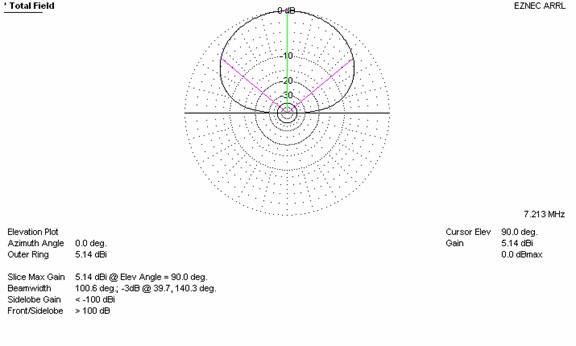
Next the antenna modeled at 10 feet. The antenna now exhibits 5.14 dBi at 90 degrees, in a vertical direction, but we now see greater gain from the sides. This is not a desired affect for NVIS. The lower angle gain brings in unwanted signals, those most likely from further away than desired for this type of operation and increases noise.
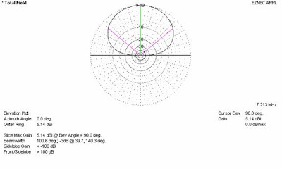 |
| Elevation Plot @ 10' |
|
|
So, what if we wanted to lower the antenna below 7 feet?
Here is a model at 4 feet above the reflectors. We see the ground losses are now having an affect on total gain for the antenna. The 90 degree gain is down to 1.38 dBi, while the pattern is nearly the same the power is now lost into the earth under the antenna.
 |
| Elevation Plot @ 4' |
|
One idea I have seen and read about is placing the antenna very close to the ground, like 6 inches off the ground without a reflector wire. The ground losses are extremely high in such a system.
 |
| Elevation Plot @ 6 inches w/o reflector |
|
I modeled the antenna at different heights:
Height (Ft.) | Beamwidth | Gain at 90 Degrees (dBi) |
10 | 100.6 | 5.14 |
9 | 100.2 | 4.81 |
8 | 99.6 | 4.4 |
7 | 99.2 | 3.89 |
6 | 98.8 | 3.26 |
5 | 98.6 | 2.45 |
4 | 98.4 | 1.38 |
As the antenna is raised the gain comes up, but the beamwidth also broadens. As the antenna is lowered, the beamwidth narrows, but the gain is decreased due to ground losses.
What about a regular dipole at ¼ wave height?
 |
| 1/2 wave dipole @ 1/4 wave height |
|
As you can see the most power is radiated at low angles and little in the upward direction necessary for NVIS.
So it seems the falt top antenna over three reflectors at a height of around 7 feet is ideal as it shapes the pattern in the desired way without excessive ground loss, all while keeping the low angle gain to a minimum.